AVG-160G air cooling units
These units are designed for natural gas cooling in gas or related industries. The device consists of two heat exchange sections made up of bimetallic finned pipes. The sections are arranged horizontally and mounted on a metal structure.
The fan drive with the wheel is placed on a separate frame. The fan wheel, rotating in the cavity of the collector, drives the air through the annular space of the sections, cooling the product.
Type of climatic version of the apparatus IV according to GOST 15150-69.
At the request of the customer, the device can be supplied in a climatic version HL category 1 in accordance with GOST 15150-69.
The metal supporting structure is designed for installation in areas with seismicity up to 7 points and high-speed wind pressure in the IV geographical region.
An example of a device symbol
Air cooler AVG-160G, material version B1, climatic version U, without product inlet and outlet collectors:
DEVICE AVG-160G-B1
The same apparatus, but material version B3, climatic version HL, with product inlet and outlet collectors:
DEVICE AVG-160G-B3-KhL with product inlet and outlet collectors
Device modification
Product inlet and outlet manifolds are only supplied to the gas industry upon request.
The devices are supplied in separate assembly units.
ТЕХНИЧЕСКАЯ ХАРАКТЕРИСТИКА ИЗДЕЛИЯ
| Коэффициент оребрения труб | 14,6; 20 |
| Условное давление, МПа (кгс/см²) | 16(160) |
| Количество теплообменных секций | 2 |
| Число рядов труб в секции | 4 |
| Число труб в секции | 194 |
| Длина труб, м | 6 |
| Число ходов по трубам | 2 |
| Поверхность теплообмена, м² | 2930, 3762 |
| Диаметр колеса вентилятора, мм | 5000 |
| Электродвигатель: | |
| тип | ВАСО02-75-24 |
| мощность, кВт | 75 |
| количество | 1 |
| Масса аппарата без коллекторов входа и выхода продукта, кг, не более | 20000 |
| Масса коллекторов входа и выхода продукта, кг, не более | 3900 |
Материальное исполнение согласно таблице 1.
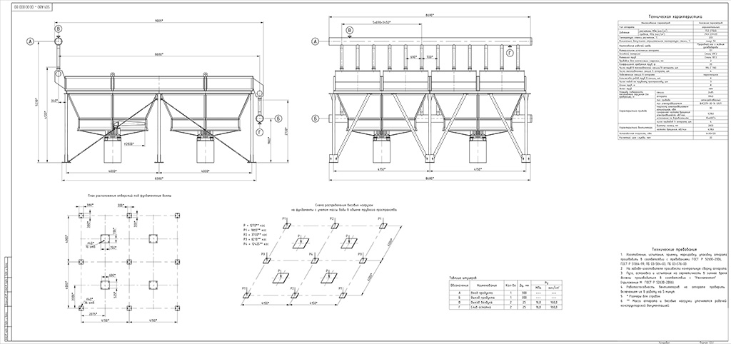
Габаритные размеры аппарата согласно чертежу 1.
Расположение отверстий под фундаментальные болты должно соответствовать указанному в монтажном чертеже предприятия-изготовителя.
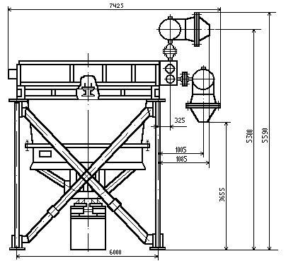 ЧЕРТЕЖ 1
МАТЕРИАЛЬНОЕ ИСПОЛНЕНИЕ Таблица 1
| Наименование | Материал | ||
| Б1 | Б3 | ||
| Климатическое исполнение | |||
| У | ХЛ | У; ХЛ | |
| Теплообменные трубы | Сталь 20 ГОСТ 550-75, ГОСТ 8731-74, ГОСТ 8733-74 | Сталь 10Г2 ГОСТ 550-75, ГОСТ 8731-74, ГОСТ 8733-74 | Сталь 12Х18Н10Т, Сталь 10Х17Н13М2Т ГОСТ 9941 – 81 |
| Коллектор секции | Сталь 20 ГОСТ 550-75, ГОСТ 8731-74 | Сталь 10Г2 ГОСТ 550-75, ГОСТ 8731-74, ГОСТ 8733-74 | Сталь 12Х18Н10Т ГОСТ 9940 – 81 |
| Коллекторы входа и выхода продукта | Сталь 20, Сталь 10Г2 ГОСТ 550-75 | ||