AVG-160 air cooling units
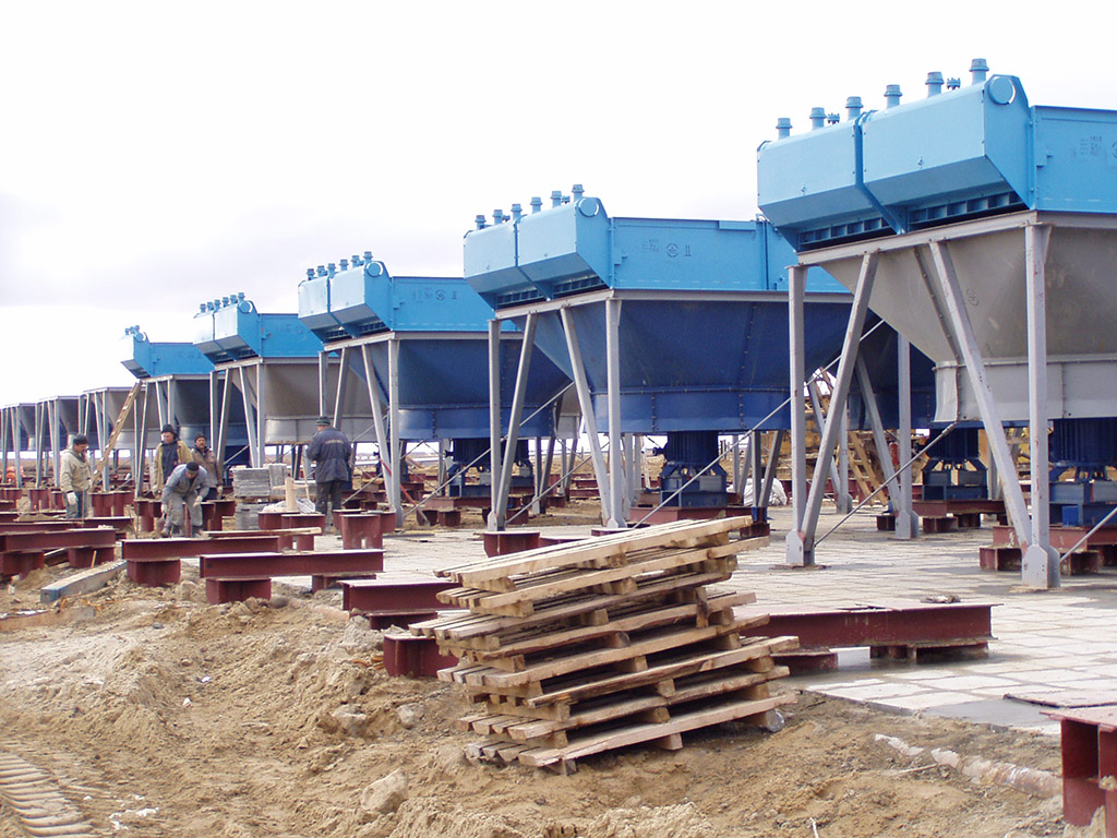
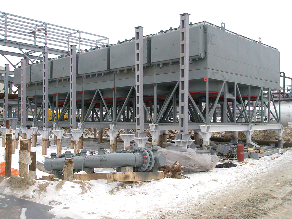
These units are designed for cooling natural gas and condensation of liquid hydrocarbons. The unit consists of four heat exchange sections made up of finned bimetallic pipes.
The device consists of four heat exchange sections made up of ribbed bimetallic tubes. Sections are arranged horizontally and mounted on a metal structure. The drive with the fan wheel is placed on a separate frame. The fan wheel, rotating in the cavity of the collector, drives the air through the annular space of the sections, cooling the air.
The devices are designed to work in microclimatic regions with a cold climate. Placement category 1 according to GOST 15150 with an average air temperature for five consecutive days in the coldest period not lower than 223 K (-50°C) with a minimum operating temperature of parts working under pressure of minus 40°C.
The devices are designed for installation in areas with seismicity up to 7 points and high-speed wind pressure in the IY geographical area.
Place an orderТЕХНИЧЕСКАЯ ХАРАКТЕРИСТИКА ИЗДЕЛИЯ
| Коэффициент оребрения труб | 20 |
| Условное давление, МПа (кгс/см²) | 17,0(170) |
| Количество теплообменных секций | 4 |
| Число рядов труб в секции | 6 |
| Число труб в секции | 195 |
| Длина труб, м | 8 |
| Число ходов по трубам | 3 |
| Поверхность теплообмена, м² | 9940 |
| Температура расчетная, м°С | 200 |
| Диаметр колеса вентилятора, мм | 2800 |
| Электродвигатель: | |
| тип | ВАС02 |
| мощность, кВт | 30 |
| количество | 4 |
| Установочная мощность аппарата, кВт | 4х30=120 |
Материальное исполнение согласно таблице 1.
Масса аппарата согласно таблице 2.
Габаритные размеы согласно чертежу 1.
Расположение под фундаментальные болты согласно чертежу 2.
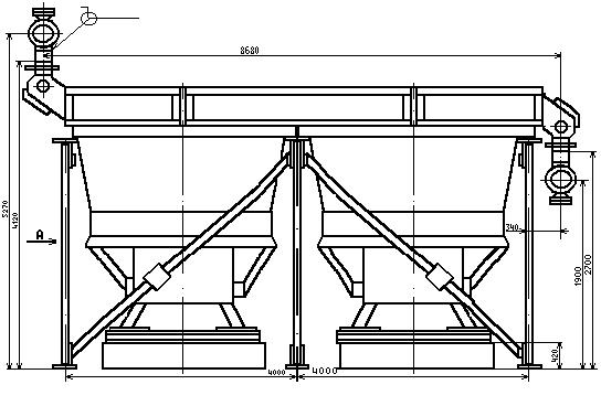
Чертеж 1
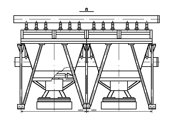
Чертеж 2
СХЕМА РАСПОЛОЖЕНИЯ ОТВЕРСТИЙ ПОД ФУНДАМЕНТАЛЬНЫЕ БОЛТЫ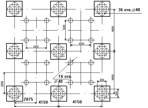 Схема 1
РАСПРЕДЕЛЕНИЕ ВЕСОВЫХ НАГРУЗОК АППАРАТА НА ФУНДАМЕНТЫ В ЗАВИСИМОСТИ ОТ МАССЫ АППАРАТА С УЧЕТОМ МАССЫ ВОДЫ В ОБЪЕМЕ ТРУБНОГО ПРОСТРАНСТВА СЕКЦИЙ И МАССЫ ОБСЛУЖИВАЮЩИХ ПЛОЩАДОК (ГРУЗОПОДЪЕМНОСТЬ ПЛОЩАДОК 200 кгс/м²)
Схема 2
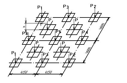 P = 2630 кгс
P1 = P2 = 4050 кгс
P3 = 8100 кгс
P4 = 13490 кгс
P5 = 26980 кгс
T <= 100 кгс - центробежная сила от неуравновешенных масс колеса и вентилятора (действует в горизонтальной плоскости)
h = 1320 мм - высота действия силы T
МАТЕРИАЛЬНОЕ ИСПОЛНЕНИЕ Таблица 1
| Материальное исполнение | Материал | ||
| Коллекторная труба | Внутренняя теплообменная труба | Наружная теплообменная труба | |
| Б1 | Сталь 10Г2 | Сталь 10Г2, Сталь 20 | Алюминий А6, АД1 |
| Б3 | Сталь 12Х18Н10Т | ||
МАССА АППАРАТОВ Таблица 2
| Обозначение | Масса, кг, не более |
| 1АВГ – 160 – Б1 | 33360 |
| 1АВГ – 160 – Б3 | |
| 1АВГ – 160 – Б1 – 1 | 37860 |
| 1АВГ – 160 – Б3 – 1 | |
| 1АВГ – 160 – Б1 – 2 | 39160 |
| 1АВГ – 160 – Б3 – 2 |